 |
Imaging Techniques |
|---|
 |
Imaging Techniques |
|---|
The reflected light microscope is the most commonly used tool for the study of the microstructure of metals. It has long been recognized that the microstructure of metals and alloys has a profound influence on many of the properties of the metal or alloy. Mechanical properties (strength, toughness, ductility, etc.) are influenced much more than physical properties (many are insensitive to microstructure). The structure of metals and alloys can be viewed at a wide range of levels - macrostructure, microstructure, and ultra-microstructure.
In the study of microstructure, the metallographer determines what phases or constituents are present, their relative amounts, and their size, spacing, and arrangement. The microstructure is established based upon the chemical composition of the alloy and the processing steps. A small specimen is cut from a larger mass (for example: a casting, forging, rolled bar, plate, sheet, or wire) for evaluation.
First, the specimen must be polished to a very high luster, free from any damage introduced by sectioning, grinding, or polishing. Otherwise, the true structure will not be revealed, and the interpretation will be inaccurate. Specimens are generally viewed in the as-polished condition first using brightfield illumination to observe those constituents that have a natural color reflectivity difference from the bulk of the metal. This procedure is commonly used to examine intermetallic compounds, graphite or nonmetallic inclusions and other small particles that might be present; e.g., nitrides, carbonitrides, and barides. Some other small precipitates that have essentially the same reflectivity as the metal may also be observed if they have a much different hardness and polishing rate than the surrounding metal. They will either stand above or below the matrix phase and can be easily observed particularly if differential interference contrast illumination (DIC) is employed. However, brightfield illumination is by far the most commonly used examination mode in metallography.
Certain metals and alloys that have non-cubic crystalline atomic structures respond well when viewed with cross-polarized light (i.e., the polarization direction of the polarizer and analyzer are 90 degrees apart to produce extinction). If a metal or alloy with a cubic crystalline structure (such as a steel) is viewed with cross-polarized light, the field of view is uniformly dark, No microstructural detail can be observed. However, if a polished specimen of beryllium, cadmium, magnesium, alpha-titanium, uranium, zinc or zirconium is viewed with crossed-polarized light, the microstructure is revealed vividly.
Metallurgical microscopes usually employ synthetic Polaroid sheet filters
for both the polarizer and analyzer. The polarizer is generally placed in
the light path before the vertical illuminator, while the analyzer is inserted
before the eyepieces. Their polarization axes are rotated 90 degrees apart
for extinction. Prism polarizers are less commonly used and more expensive
but generally produce superior results. Unfortunately, they are rarely available
as an accessory for metallurgical microscopes. As an example of polarized
light examination, Figure I shows an as-polished (non-etched) specimen of
polycrystalline beryllium viewed with two different polarized light
setups.

|

|
Figure 1. Influence of polarized light setup on image quality and exposure time (Tri-X Ortho, 320 ISO, 4 x 5-inch sheet film) using (top photo) Polaroid filters for polarizer and analyzer - 32 s exposure; and, using (bottom photo) an Ahrens prism polarizer, a Berek prism pre-polarizer and a Polaroid filter analyzer - 25 s exposure and best Image (also best color development). (5Ox)
Figure 1 (top photo) shows the structure viewed using Polaroid filters (in the crossed position) for both polarizer and analyzer photographed with Kodak Tri-X Ortho 4 x 5-inch sheet film (32 s exposure, 320 ISO). The image is flat and devoid of color (images are shown here in black and white). Figure 1 (bottom photo) shows the results obtained using an Ahrens prism polarizer and a Berek prism pre-polarizer. It is excellent with good color development (although shown here in black and white) with a 25 s exposure. A Leitz Orthoplan mineralogical microscope was used for this work, While prism polarizers and pre-polarizers are more expensive than Polaroid sheet filters, they do provide the ultimate in polarized light quality (good strain-free optics are also required).
Some of the metals that respond to polarized light can also be etched
to reveal the microstructure. However, the microstructure often is revealed
better with crossed-polarized light examination of an as-polished, non-etched
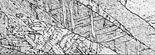
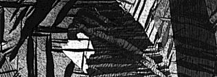
specimen. Figure 2 demonstrates this using an as-cast zinc specimen.
|
|
Figure 2. Microstructure of as-cast zinc containing mechanical twins (Neumann bands) viewed with (top photo) brightfield illumination after etching; and, with (bottom photo) crossed. polarized light without etching. (5Ox)
Figure 2 (top photo) shows the columnar as-cast structure containing
mechanical twins (the lenticular bands within the coarse, elongated grains)
viewed with brightfield illumination after etching with an aqueous solution
containing CrO3, and Na2SO4. In comparison,
Figure 2 (bottom photo) shows the microstructure revealed using crossed-polarized
light examination of a non-etched specimen. Both clearly reveal the structure,
but the polarized light image is much more dramatic.
Crossed-polarized light has limited usage in metallography because many metals and alloys have cubic crystal structures. However, some second phases may be non-cubic and will respond nicely to polarized light. Nodular graphite in ductile cast iron is commonly studied using crossed-polarized light because the growth pattern of the graphite is revealed dramatically.
In some cases, etched metals with a cubic crystal structure can be examined
beneficially with cross-polarized light. Tint etched specimens are often
viewed in this way generally with a sensitive tint plate inserted in the
light path to enhance color effects. Some structures etched with ordinary
chemical reagents respond nicely to polarized light. For example, fine pearlite
in steels or other fine lamellar eutectic or eutectoid structures respond
to polarized light, although this may not reveal anything not already observed
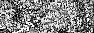
with brightfield illumination. Figure 3 shows an example where the eutectic
cells in gray cast iron, which could be observed with brightfield illumination
(Figure 3 top photo) were further emphasized using polarized light (Figure
3 bottom photo).
|

|
Figure 3. Microstructure of gray cast iron etched with 2% nitric acid in ethanol and viewed with (top photo) brightfield illumination; and, with (bottom photo) crossed polarized light. (100X)
Go To: |
[FAQ] |
[Home] |
[Vendors] |
|---|